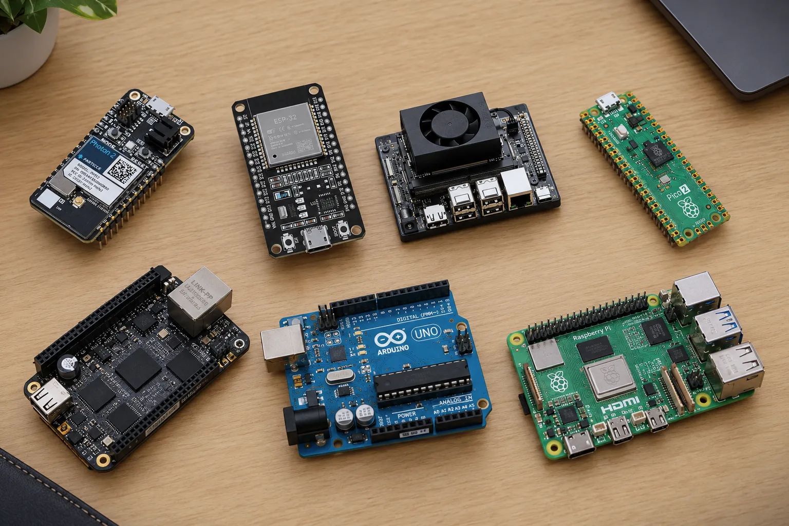
Open a blank sheet and list the devices you plan to connect. Two encoders, a motor driver, an inertial sensor, and a radio can consume interfaces in ways that a processor-speed comparison will not reveal. For each device, write down the signal type and the required voltage.
Make an interface budget
Separate a connector’s physical pins from the hardware functions assigned to them. A pin may support several functions, while your program can use only one of those functions at a time. Read the board pinout and the microcontroller documentation together. Mark conflicts before you draw the wiring diagram.
Include the tools you use during development. A serial console and a debugger need connections too. Reserve access to reset and programming pins so you can recover a board after a firmware mistake. Check power requirements for the complete assembly instead of treating USB power as a permanent plan.
Test the narrowest requirement
Build a small program around the hardest interface requirement. Count encoder edges at the expected rate, or stream sensor data while logging timestamps. Measure the behavior on your chosen hardware before expanding the program.
Keep the resulting pin map in the project repository. A teammate should be able to match a wire label to a firmware constant without asking which version of the board you used. Record the exact board revision and the source of its documentation.
Have a correction or a different result? Write to the editor.